
The two most common electric techniques used with the Dimension Icon microscope are Electric Force Microscopy (EFM) and Surface Potential Detection. Both modes make use of Interleave and LiftMode procedures. Ensure you are familiar with before attempting electric measurements.
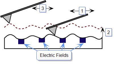
Electric techniques are similar to Magnetic Force Microscopy (MFM). The two-pass LiftMode measurement allows the imaging of relatively weak but long-range electrostatic interactions while minimizing the influence of topography. In the case of MFM, the system is measuring long-range magnetic fields. LiftMode records measurements in two passes, each consisting of one trace and one retrace, across each scan line. First, LiftMode records topographical data in TappingMode on one trace and retrace. Then, the tip raises to the Lift Scan Height, and performs a second trace and retrace while maintaining a constant separation between the tip and local surface topography.
Electric Force Microscopy (EFM) measures variations in the electric field gradient above a sample. The sample may be conducting, nonconducting, or mixed. Because the surface topography shapes the electric field gradient, large differences in topography make it difficult to distinguish electric field variations due to topography or due to a true variation in the field source. The best samples for EFM are samples with fairly smooth surface topography. The field source could be trapped charges, applied voltage, and so on. Samples with insulating layers (passivation) on top of conducting regions are also good candidates for EFM.
Bruker provides several methods for surface potential imaging:
The sample should be electrically connected directly to the chuck, so that it can be held at ground potential (normal operation) or biased through the chuck. The sample can either be mounted directly on the chuck or onto a standard sample puck using conductive epoxy or silver paint as shown below:

Figure 1: Schematic diagram showing how to electrically connect a sample onto a sample puck.
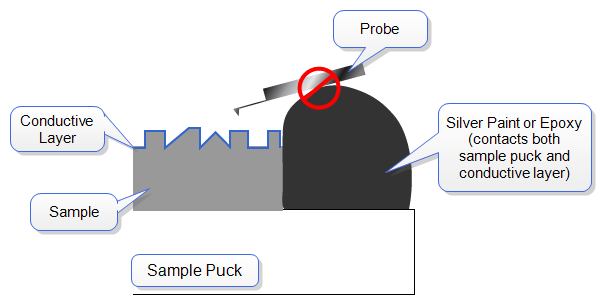
Figure 2: Schematic diagram showing how NOT to electrically connect a sample onto a sample puck.
| www.bruker.com | Bruker Corporation |
| www.brukerafmprobes.com | 112 Robin Hill Rd. |
| nanoscaleworld.bruker-axs.com/nanoscaleworld/ | Santa Barbara, CA 93117 |
| Customer Support: (800) 873-9750 | |
| Copyright 2010, 2011. All Rights Reserved. |
 Related Topics